A pergola drawing workflow normally moves from confirmed project inputs to a module layout, post and roof-direction coordination, product profile reference, drainage and accessory interfaces, drawing confirmation, fabrication, packing and installation reference. Catalogue drawings help select a system, while the approved project drawing controls the confirmed order. Neither replaces site-specific structural, foundation or local approval work where that is required.
Three different drawing stages
These documents solve different problems. Keeping them separate prevents an early catalogue reference or quotation sketch from being mistaken for the drawing used for production or local structural approval.
| Drawing stage | Main purpose | What it does not mean |
|---|---|---|
| Catalogue / profile reference | Compare roof systems, blade, post and beam profiles and catalogue module references during early model selection. | It is not approval that a catalogue maximum is suitable for every site. |
| Project / production drawing | Coordinate confirmed dimensions, modules, post positions, roof direction, drainage, accessories and components that will be produced for the order. | It does not by itself verify an existing building, foundation or every local code requirement. |
| Local structural / permit review | Review project-specific loads, supporting construction, anchors, foundations and local approval requirements where applicable. | It is not replaced by a factory catalogue sheet or product profile drawing. |
From project input to production
Project inputs
Start with dimensions, clear height, site plan or marked sketch, installation type, location, required roof system and accessory scope.
Next planning step
Aluminum Pergola Thermal Expansion: Why Connection Details Matter: Understand thermal movement in aluminum pergolas and the questions to ask about connections, glass interfaces and installation clearances.
Module layout
Divide the project into practical bays and confirm where posts can be placed, which modules connect and how each zone is identified.
System interfaces
Coordinate blade or roof movement direction, drainage, ZIP screens, glass, lighting, controls, wiring and other interfaces before fabrication.
Drawing confirmation
Check dimensions, module references, scope and project assumptions against the latest site information before releasing the order for production.
Fabrication & packing
Production and package identification can follow the same module or bay references used on the approved project drawing.
Installation reference
The installation team works from the latest approved revision while local site, structural, drainage and electrical responsibilities remain coordinated on site.
Real project evidence: Nigeria JY250
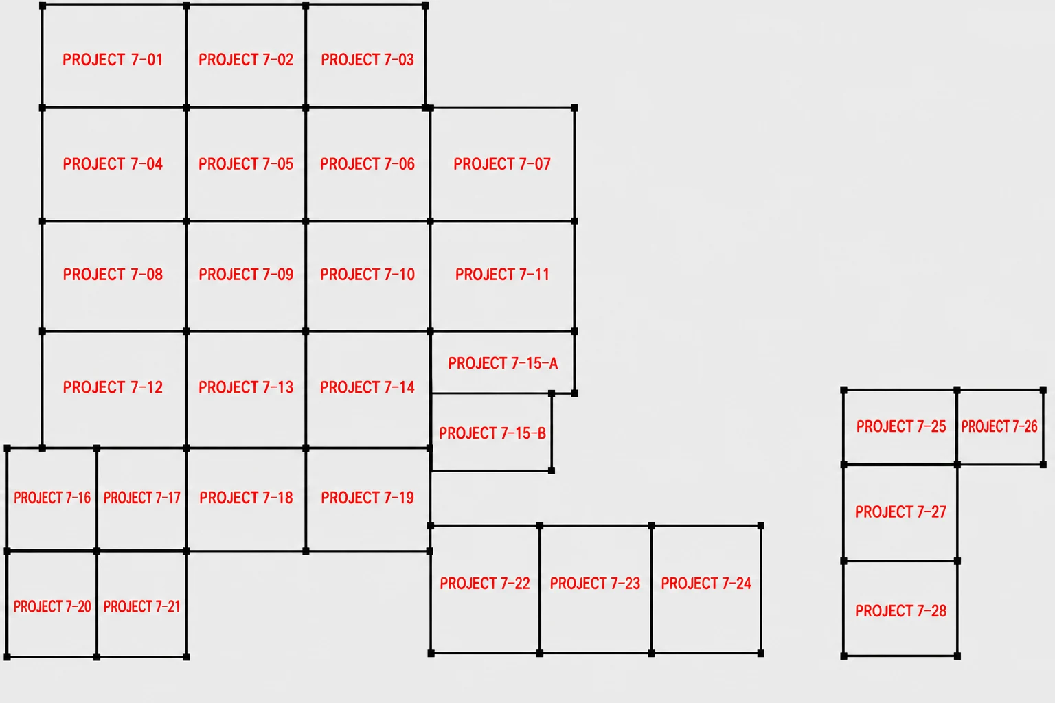
The Nigeria JY250 project is a real example of why drawing coordination matters on a large multi-module pergola. The complete area was treated as one project, then divided into individually identified pergola zones so the technical, production, packing and installation teams could use the same references.
Catalogue profile drawings are selection references
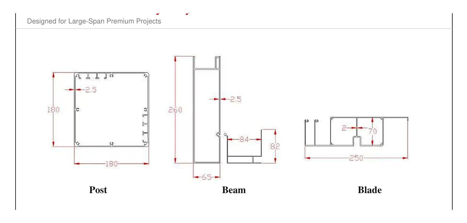
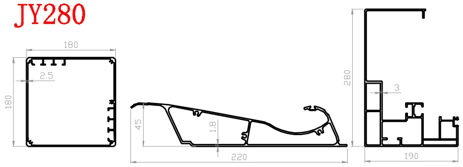
Profile drawings are useful before the final project drawing because they make the selected system and its main component sizes explicit. They remain product references: site conditions, module layout, supports, drainage and local load requirements still need project review.
What to confirm before drawing approval
- Overall width, projection, clear height and finished-level references.
- Freestanding, wall-mounted or connected-module arrangement.
- Permitted and restricted post locations.
- Roof or louver movement direction for every module.
- Drainage direction, outlet positions and local discharge route.
- ZIP screens, glass, lighting, sensors, controls and electrical interfaces.
- Model, finish, quantity and module identification.
- Known wind, snow, foundation, wall or permit criteria for local review.
For the information needed before this stage, use the Pergola RFQ checklist . For oversized or connected layouts, see the large-span module planning guide .
Factory drawings and local structural approval are different
A factory project drawing coordinates the pergola product and the confirmed order. It can show modules, component relationships, post positions, roof direction and product interfaces. It should not be read as verification of an existing wall, foundation, hidden site condition, local wind or snow criteria, anchor design, waterproofing, electrical compliance or permit requirement unless that work is specifically included and confirmed for the project.
Those site-specific responsibilities must be handled by the appropriate local project parties where required. The installation team should also use the latest approved drawing revision rather than an early sales sketch or obsolete layout.
After drawing approval
Once the project configuration and order details are confirmed, the drawing reference can carry into production and packing. For multi-module orders, module identification helps group components and lets the receiving or installation team match packages back to the project layout.
See the production lead-time guide for the factory sequence after confirmation, and the export packaging guide for module and package identification.
This page describes the current JY Home Shade drawing and production coordination workflow. The Nigeria JY250 layout and current catalogue profile drawings are used as public examples. Public CAD/DWG downloads are not offered on this page.
Final structural suitability, foundations, supporting construction, anchors, local compliance and installation conditions remain project-specific.
Technical review: JY Home Shade factory product team · Last reviewed: 20 September 2026
Send the project plan before production
Share the dimensions, site or architectural plan, permitted post positions, roof system, accessories and project location. The factory team can review the module arrangement and drawing inputs before production.