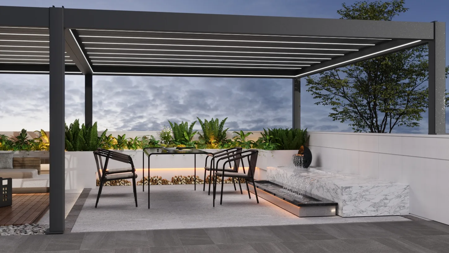
Before ordering a motorized pergola, confirm destination voltage and frequency, number of roof modules and motors, independent or grouped operation, controller and switch locations, optional sensors, lighting and accessory circuits, cable entry routes, isolation, weather protection and commissioning responsibility. Send this schedule to both the factory and the qualified local electrician.
Map every electrical item to a module or opening
| System | Decision before production | Local coordination |
|---|---|---|
| Roof motor | Module served, motor position and control group | Supply, isolation, protection and access |
| Controller / receiver | Compatible equipment and protected location | Mounting access and final connections |
| Wall switch / remote | Individual, grouped or master operation | User location, labels and handover |
| Weather sensor | Required function, compatibility and operating logic | Position, testing and owner instructions |
| Integrated LED | Beam location, zones, color temperature and dimming request | Driver access, circuit and control interface |
| Screen, fan or heater | Opening or beam served and confirmed equipment data | Dedicated loads, clearances, switching and local compliance |
Electrical information to send the factory
- Country and project destination.
- Available voltage and frequency confirmed by the local electrician.
- Numbered roof modules and motor quantity.
- Which modules operate independently and which operate as groups.
- Required wall switches, remote controls, master controls or sensors.
- Lighting zones and every motorized accessory by opening.
- Preferred cable entry points and concealed routes.
- Equipment schedules for third-party fans, heaters or automation interfaces.
Do not combine loads by assumption
Roof motors, LED drivers, ZIP screens, fans and infrared heaters do not automatically belong on one circuit. They may have different loads, switching methods, protection and isolation needs. Heaters in particular can change the electrical scope substantially. Use the final equipment data and local rules to create the circuit schedule rather than estimating from an early rendering.
Plan controls for multi-module pergolas
A connected pergola may have several roof zones. Grouped operation can be convenient, but independent control helps with commissioning, service and areas used at different times. Number each module on the plan and use the same identifiers on motors, controllers, cables, drawings and handover records. If one remote or building automation interface is requested, define what happens to each zone rather than writing only "all connected."
Coordinate cable routes with drainage and moving parts
Choose cable routes before holes, brackets and finishes are finalized. Keep wiring coordination separate from internal drainage paths and away from louver movement, sharp edges and inaccessible joints. Mark where cables enter the pergola and where controllers or drivers remain serviceable. Any site-made opening should follow the approved detail and preserve required protection.
Commissioning and handover checklist
- Verify equipment labels against the approved electrical schedule.
- Confirm supply, protection and isolation before energizing.
- Test each roof zone independently before grouped commands.
- Check travel, limits, obstruction clearances and unusual noise.
- Test lights, screens, sensors and other accessories one system at a time.
- Record controller, remote and sensor assignments.
- Give the owner operating, weather, isolation and service instructions.
- Keep final drawings, product data and test records together.
Factory scope and local electrician scope
The factory can provide confirmed product information, component identification, project drawings and available installation media for the order. The local electrical team remains responsible for compliant site supply, cable selection, protection, isolation, final connections, testing and any integration with local controls or building systems.
Frequently asked questions
What information is needed before production?
Provide destination, power characteristics, modules, control groups, accessories, cable routes and local electrical requirements. Confirm exact values in the approved product documents.
Can motors, lights, fans and heaters share one circuit?
Do not assume so. A qualified local electrician should schedule circuits and protection from the final equipment loads and local requirements.
Can several modules operate together?
Grouped operation may be possible within the confirmed control system, but independent operation should also be considered for service and zone control.
Who completes the site connection?
Qualified local electrical personnel should complete and test the site supply, isolation, protection, final wiring and commissioning.
Can I open or close a motorized pergola during a power outage?
Normal motorized operation requires power. Before ordering, ask what the specified motor and controller allow during an outage and after power returns. Manual operation or backup power must be confirmed for that configuration; neither should be assumed. Do not force the roof or improvise a power connection.
Can I connect my pergola to a smart home system?
Compatibility needs confirmation for the exact motor, controller and proposed interface. Send the name of your home automation system, the functions you want to control, and whether roof modules, screens and lights should operate separately. A supplied remote does not establish smart home compatibility. Agree the integration and testing responsibilities before ordering.
This page is a coordination checklist, not a wiring design. Never select conductors, protective devices, enclosures or connection methods without confirmed equipment data and applicable local requirements.
Technical review: JY Home Shade factory product team | Last reviewed: 3 September 2026
Next planning step
What Happens to a Motorized Pergola During a Power Outage?: Check roof movement, manual operation, weather sensors, backup power and restart instructions before choosing a motorized pergola.
Send the electrical schedule with your layout
Number each roof module and accessory, then add destination, power supply and preferred control groups.